Automating Pneumatic Press Operation for Battery Module Manufacturing

Introduction
The Project
This project report is the culmination of a year-long capstone project in collaboration with Corvus Energy. The goal of the project was to design the automation system for a pneumatic press station which sits at Corvus’s main manufacturing line in Richmond, B.C., Canada. Corvus Energy, founded in 2009, is a company whose main purpose is the manufacturing and sale of Energy Storage Systems (ESSs). Their main market focus relies in the maritime industry, which is directly impacted with regulatory compliance and emissions control in different geographical regions worldwide (Corvus Energy, 2022). According to Corvus (2022), “more than 90% of large commercial hybrid vessels utilize a Corvus Energy ESS”.
An automation system was designed, costed, and proposed to the client. This system was designed to address all of the client’s needs and wants in regard to automatic processing of the battery modules.
System Characterization
Given that the project consists primarily of retrofitting the current capabilities at Corvus Energy, a preliminary characterization of the system was performed. This initial assessment allowed for a coherent understanding of the machinery available and its interconnections to the assembly line. Details pertaining to Corvus Energy’s manufacturing capabilities are left out of this article to protect it’s proprietary information.
Value Proposition
Immediately after the initial visit, the client’s needs became apparent. This section will explore the client’s needs, and how these would have to be addressed in a potential solution.
Needs Assessment
To be successful, the proposed automation system would have to comply with certain needs. These were mainly discussed during the project’s kickoff meeting and established within the first few weeks of the project, alongside the client.
The primary need identified was that of having a fully automatic system that could process modules with no human interaction. This functional need was the main driver of the project, and what the authors’ ultimate role in it was. The specifics of the implementation – how the goal was to be achieved – were left largely unspecified by the client, with some notable exceptions.
Design Objectives
With the needs and potential benefits in mind, the following design objective statement was defined.
The press must be automated enough so that it can detect the presence of incoming modules, identify the state of said module and adapt to its required processing parameters. The system should be able to vary the pressure and time setpoints to those requested by the MES, while defaulting to pre-retrofit values if unspecified. The press station should be designed in such a way that it maximizes operator safety, and productivity, while minimizing capital costs.
Proposed Solution
Knowing the client needs, requirements, and performance criteria, a solution could be crafted.
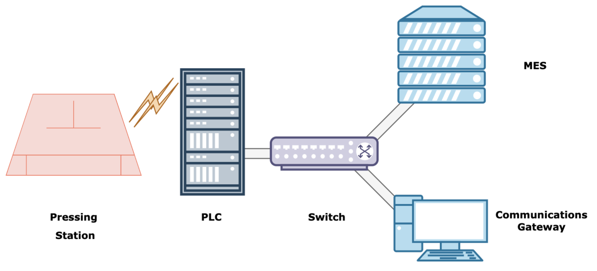
There are three key components in this system: A Programmable Logic Controller (PLC), a Communications Gateway (CG), and the Press Station (PS, press). All three elements are essential to both manual and automatic operation of the press. These components are connected as per the following figure.

Functional Decomposition
Functional decomposition can be performed on the components to better understand how each addresses different aspects of the automation system. The following list summarizes the roles and responsibilities of each of the above devices.
- PLC (Programmable Logic Controller)
- Control actuators that interface with the press station. o Monitor press station parameters.
- Monitor processing parameters while pressing a module o Monitor status of safety components
- CG (Communications Gateway)
- Poll status of PLC’s inputs and state.
- Liaise between the MES and the PLC
- Poll processing parameters for an incoming module
- Instruct the PLC when and how to process an incoming module. o Maintain a heartbeat with the PLC
- MES (Manufacturing Execution System)
- Provide processing parameters to the CG
- Record alarms
- Record actual processing parameters
In summary, the PLC handles all the physical sensors and actuators which are directly connected to the press, as well as low-level logic regarding these. The CG handles the high-level logic of the system, relaying information to and from the MES and PLC, ensuring that the processing parameters for each module are met. The MES acts as the source of the ideal processing parameters, as well as a historian for alarms and actual processing parameters.
System Development
As alluded to in the preceding section the proposed solution to Corvus’s desired automation system is a multi-faceted multidomain approach. This section will explore the technical details surrounding this solution. The software-level details of the implementation are described subsequently. Concerns regarding hardware selection are left out of this article.
Network Topology
The implemented system uses both digital, discrete, and analog signals for communications. All digital communications use Ethernet as the physical layer (CAT 5e and 6). The CG and MES communicate via TCP, while the CG and PLC communicate via MODBUS TCP. Additionally, the PLC uses Analog 4-20mA signals to control the piston valves, and discrete 0/24VDC signals to monitor the light curtains and E-stop button.
The following diagram (Fig. 14) illustrates the network architecture for the implemented system, as well as the self-assigned IP addresses of the respective devices. The switch is an unmanaged 5-port switch from AutomationDirect (model SE2-SW5U) and forwards all the messages within the subnetwork to the correct recipient regardless of protocol. It is powered with 24VDC via an external PSU.
The PLC and CG both have self-assigned static IP addresses within the Press Station Subnetwork 172.16.16.0/24 (/24 indicates a subnet mask of 255.255.255.0). As such, these devices can communicate with each other without a router. The subnetwork is private in nature, due to its adherence to the RFC 1918 standard. Cybersecurity concerns outside of this network, such as routing from other networks or the internet, were not considered as part of the project’s scope.

Software
There are two distinct yet coupled domains to the automation system’s software implementations. The first of these is that which pertains to the CG, while the other pertains to the PLC. As briefly mentioned in previous sections, the CG handles all the compatibility aspects that arise when attempting to connect a PLC to the Manufacturing Execution System (MES). On the other hand, the PLC handles the physical sensing and actuation as relevant to the pressing of modules. Both devices work together to address the client’s performance requirements.
The entirety of the software developed for the CG was written and tested on Python 3.8. The CG, which is a Raspberry Pi Model 4b single board computer, was prepackaged with Ubuntu Server 20.04.4 LTS (Focal Fossa). This version of Ubuntu Server is lightweight, enterprise-ready, and will be supported through hardware and maintenance updates until 2025, and with extended security maintenance until 2030.
Communications Gateway
The main role of the CG is to mediate between the PLC and MES. To be performant in this role, the CG had to monitor the PLC and MES continuously and independently. The CG was programmed as a multi-threaded application. This allows the CG to execute tasks in a concurrent and non-blocking manner.
Concurrency thus plays a large role in the automation system and proves advantageous given the large amount of external read/write operations performed on the PLC and MES. Three threads were defined to handle specific tasks in the automation system, they are summarized in the following table.
The CG can communicate with the PLC since they both implement the MODBUS TCP communications protocol. This protocol, which is standard for several automation ventures worldwide, uses Ethernet/IP as the physical layer and TCP as the transport-layer protocol of the OSI (Open Systems Interconnection Model).
Throughout this section, the foo formatting style is used to denominate code elements such as variable names, types, and packages. Additionally, this section uses the PEP 484 type hint naming convention, where foo:bar indicates name:type.
| Thread Name | Role |
|---|---|
th_PLC_heartbeat | Monitors the status of PLC-CG communications and updates threads when first set. |
th_PLC_brain | Handles all PLC IO-bound operations and data extraction. |
th_MES_brain | Handles all MES IO-bound operations and data logging. |
Heartbeat Algorithm
A heartbeat algorithm was implemented into the CG in order to assess the status of the PLC ↔ CG communications. An independent thread on the CG programming attempts a read and write operation from and to the PLC every 5 seconds. If at least one of the read/write operations fails, the CG notifies the other threads in order to take action. The status of the connection keeps on being monitored every 5 seconds in order to detected potential reconnections of the communications channel.
PressStation.py
This file fully defines all details and aspects of the press station as a python class. It implements methods such as start_pressing() and stop_pressing() which commence or stop pressing, respectively. Additionally, it provides methods to update processing parameters on the press itself. An important feature of this class is that any object of type PressStation (e.g., myPress:PressStation) can be fully serialized into persistent storage. This allows constant backups to be taken which include the press’s latest parameters and state. This was achieved by developing this class, as well as some helper elements to it, in a manner that is compatible with Python’s pickle module. Backup features were not implemented at this stage.
PLCComms.py
This file implements all methods which are pertinent to CG <–> PLC communication. It includes the previously defined heartbeat algorithm, as well as the plc_get() and plc_set() methods. These two methods allow for I/O operations on the PLC, and use an open source clickplc package, which relies on pymodbus and asyncio as its main dependencies. A few modifications were made to make the methods implemented in this package thread safe via the heartbeat algorithm.
Dependencies
The implemented software relies on several dependencies. All dependencies are open source and available for commercial use, released under GNU General Public License v2.0, or similar; allowing for modification, redistribution, and commercial use of the software. The following figure shows the dependency diagram for the implemented software.

Prototyping
A prototype was developed to test the accuracy and validity of the proposed automation system. This prototype included hardware and software components to it and attempted to include as much of the elements developed for Corvus.
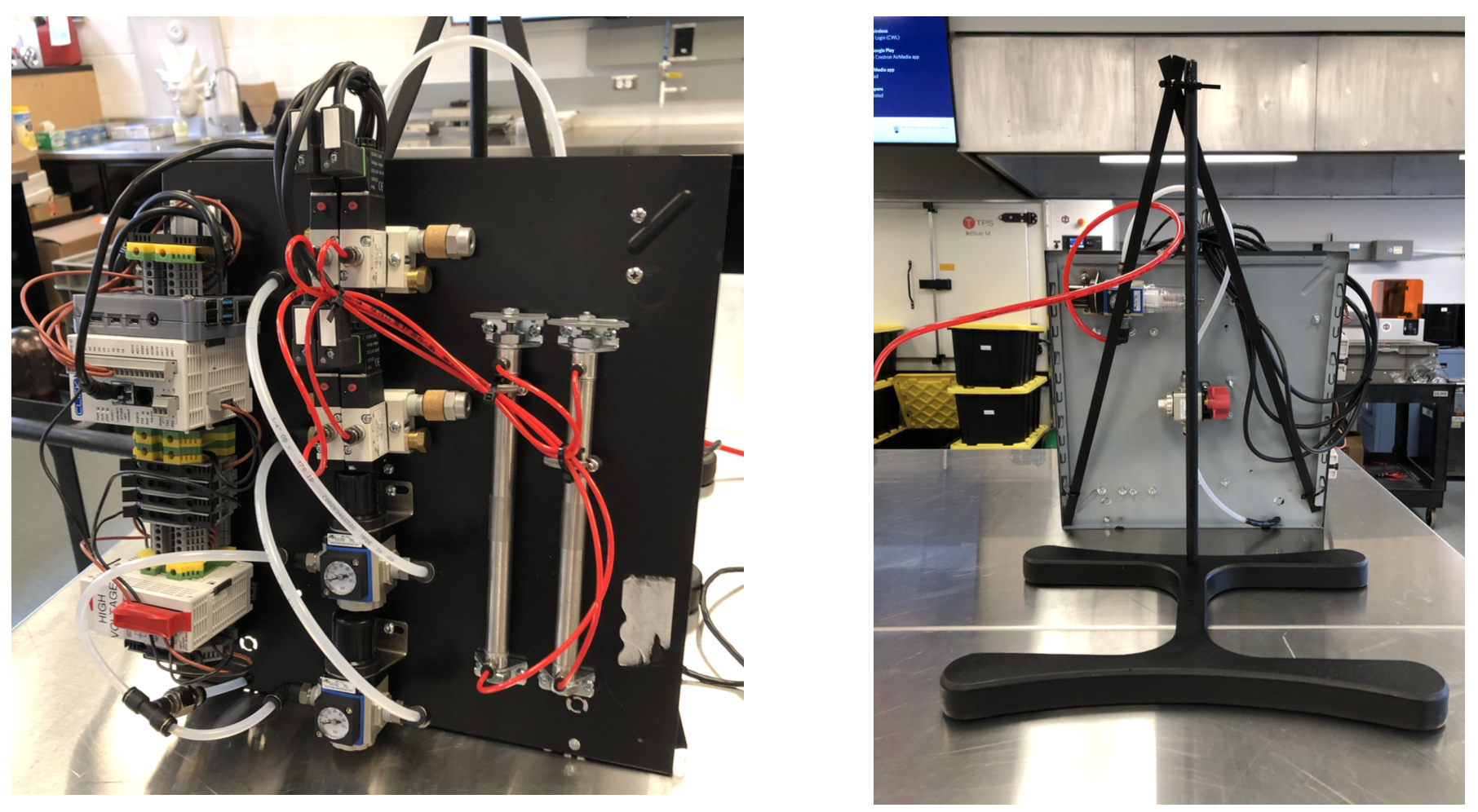
In terms of hardware, a test panel – constructed from a recycled computer case – was built, which included some of the main elements in the automation system. Some key elements were omitted from testing, such as the load cells and linear transducers since these are fixed on- site and currently in use by Corvus. The following figure shows the test panel.

A main regulator set to \(50\ psi\) is attached to the back of the panel. This regulator serves as the main feed point for incoming compressed air (or nitrogen). Immediately following the regulator is a shutoff valve, which was added to provide a way to isolate the pneumatic system for safety. This was important given that the prototype is set to be presented at a public-facing event during UBC’s Applied Science Design & Innovation Day.
To mimic the press station, two pistons were added to the system, each having their own set of valves for extension and retraction, as well as an independent regulator. The regulators were fixed to \(25\ psi\) for compatibility with the selection of valves and pistons. An important departure from the real press station is the fact that two valves are available for piston position control in the prototype. The real-world counterpart to the prototype has a single valve per piston, given that its retraction is gravity driven.
In terms of software, a simple, hardcoded demo was added to the CG to simulate typical commands from the MES. This code would simply generate a random number as the pressing duration and send the command to the PLC for actual engagement of the pistons. The prototype was mounted on a recycled steel base which was spray-painted black for aesthetic purposes. The main regulator and shutoff valve were positioned at the back of the panel for added safety in case of failure.
Client Deliverables
Given the scope of the project, the core of the end deliverables was in the form of documentation and specifications regarding the developed automation system. This section will provide an overview of all the deliverables which were offered to the client at the culmination of this project.
Operations Philosophy
The operations philosophy document, which contains the approaches to control and strategies as designed, was delivered to the client. This document was reviewed and approved by the client before the project’s culmination and contains the client’s final requested changes.
Controls Narrative
The controls narrative serves as the main software level specification of the project. It contains the core of the technical depth in terms of software and control, as well as the complete design specification of the press station’s automation subnetwork.
Control Panel and Loop Drawings
A collection of control panel, loop, and network diagrams was developed and delivered to the client. The control panel diagrams include the full assembly and wiring specification of all the elements in the control panel. The loop drawings include all the field elements which are necessary to the press’s automated operation as well as their wiring.
MFMEA
A Machine Failure Mode and Effects Analysis was delivered to the client as the main form of risk assessment of the project.
Conclusion
After a year-long project in collaboration with Corvus Energy, the design of an automated system for the operation of a pneumatic press was achieved. The automation system was designed and implemented across two main control devices, a Communications Gateway, and a Programmable Logic Controller. Each of these two devices was in charge of a particular aspect of the automation system, with the CG handling all high-level processing logic, and the PLC handling sensing and actuation in the press.
All relevant hardware in the system was costed and itemized in a Bill of Materials. Additionally, the hardware layout and wiring were specified in a set of technical drawings which included both the in-panel and field elements. An Operations Philosophy and Controls Narrative were developed in order to define the approaches and strategies of the automation system and how they were achieved in practice. Finally, a risk assessment in the form of a Machine Failure Mode and Effects Analysis was carried out to identify and minimize the risks undertaken with this project.
A prototype which incorporated the most important elements of the project was developed as the culmination the project. It exhibited the relevant control and field elements, as well as the software required to make the system operable in harmony.