Design and Simulation of 5-Axis Machining Process for Complex Part

Welcome to a detailed exploration of a technical project that delves into the intricacies of designing and simulating a complex 5-axis machining process. Our objective was to craft a comprehensive process that effectively machines a sophisticated part, exploring the realms of geometry, material properties, tool selection, and simulation.
Introduction
At the heart of this project lay the challenge of creating a 5-axis NC machining process for a complex part using Siemens NX and verifying it through simulation using Vericut on a Haas UMC750 vertical 5-axis machining center. This intricate part comprised diverse features such as fillets, chamfers, slanted walls, pockets, and closed angle corners, all crafted from Al 6061 material. The project’s core objectives encompassed tool selection, fixture design, optimal machining sequence in NX, and a meticulous comparison of the simulated part with the original design.

Model Review
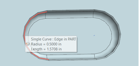
Diving into the dimensions and features of the part, we encountered a square base topped with a cylinder and an intricate cup-like feature. This feature was adorned with ellipsoidal pockets, circular pockets, and precise chamfers. Each dimension and curvature was meticulously detailed to ensure accuracy and efficiency throughout the machining process.
Fixture and Tools
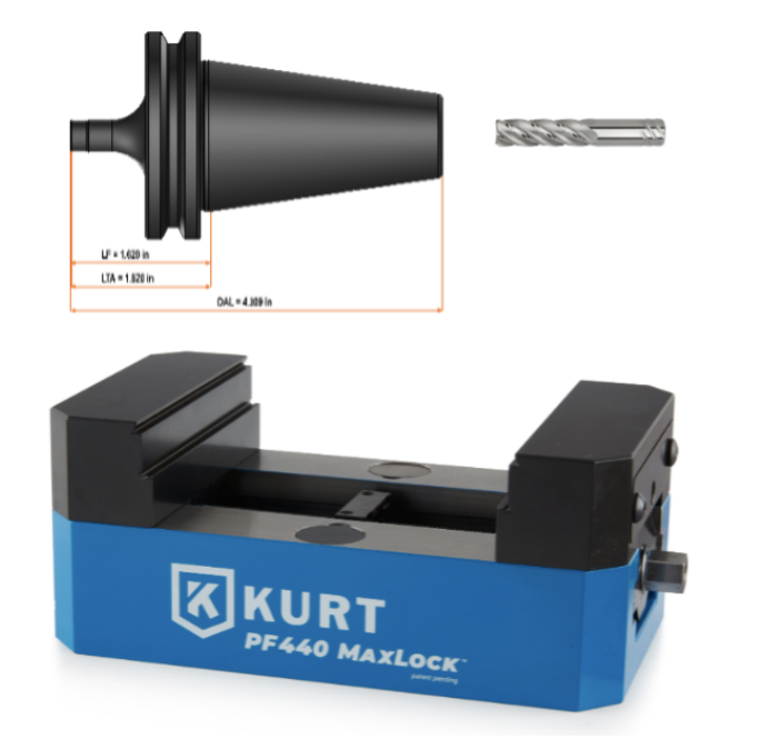
To ensure our machining endeavors were precise and efficient, we selected the Kurt MaxLock 5-Axis Vise – PF440D fixture, facilitating secure clamping on the Haas UMC 750 machine table. Our tool selection from Kennametal in Machining Cloud was tailored to suit the challenging characteristics of Al 6061. Tools like AADE Double Rake Flute Form, KOR5TM DA 5 Flutes, DUO-LOCKTM MaxiMetTM ABBE Ball Nose, and others were harnessed to ensure optimal material removal and surface finish.
Machining Process Overview
Our journey through the machining process was punctuated with a series of operations, each meticulously tailored to tackle specific geometries and features of the part. From cavity milling to roughing and finishing of walls, pockets, and chamfers, we navigated the intricate landscape of the part’s geometry. Every tool, pass, and feed rate were strategically chosen to ensure precision and efficiency.
Vericut Simulation
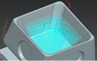
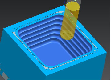
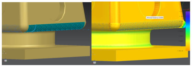
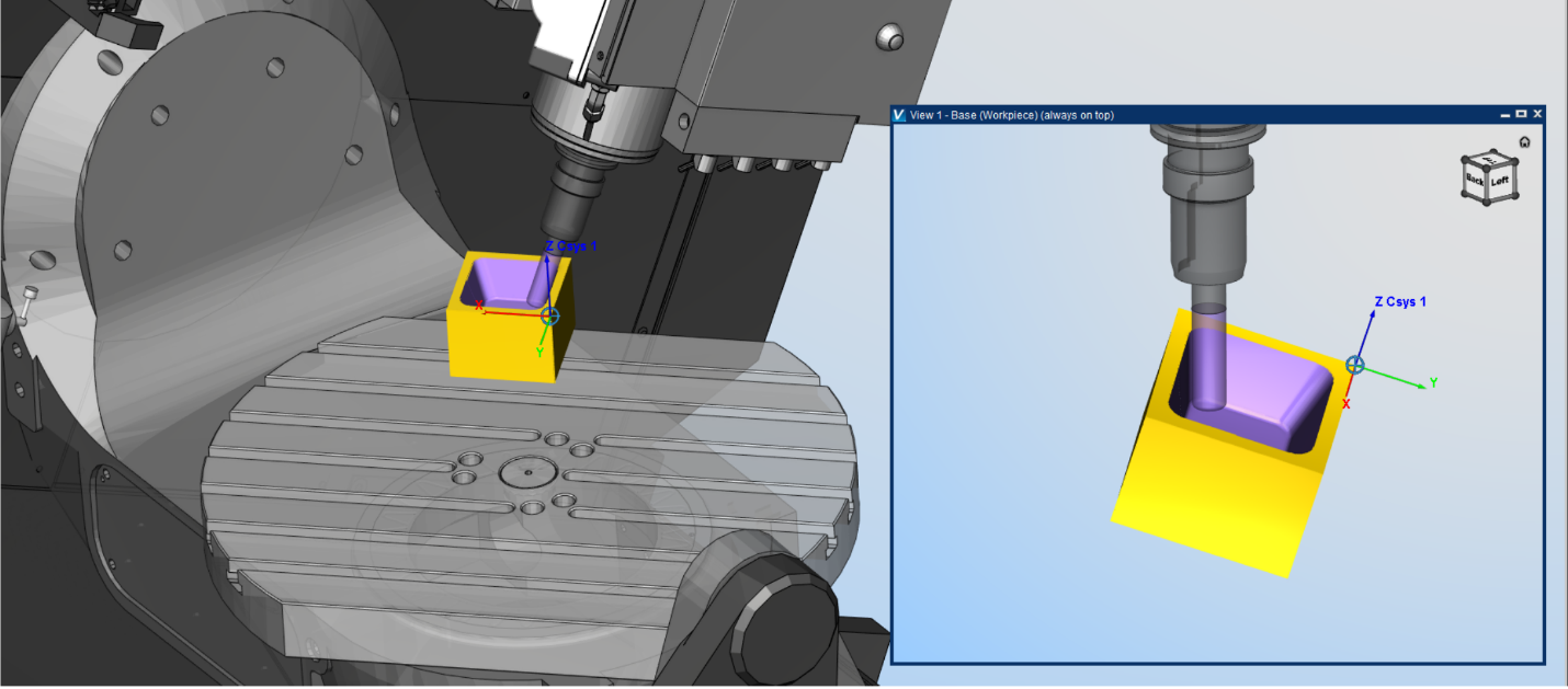
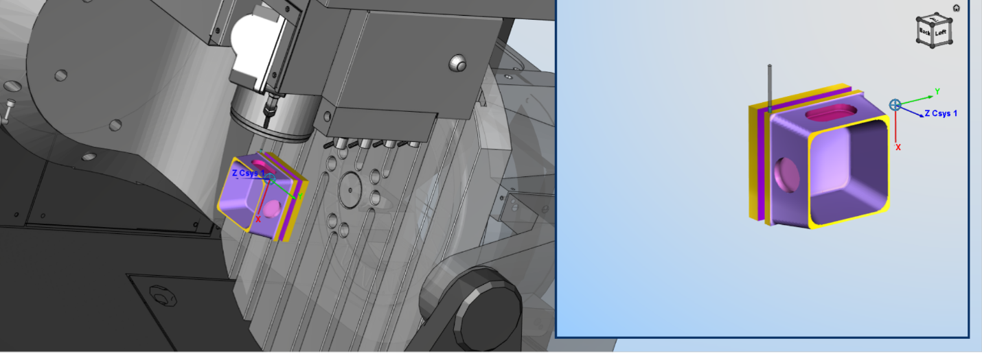
Vericut became our testing ground, where our meticulously designed NC program and tools were put to the test. Through simulation, we confronted and resolved a range of challenges, from tool-path optimization to post-processing issues. In this virtual realm, we witnessed the fruition of our design, learning from collisions, gouges, and damages that helped us fine-tune our approach.
Conclusion
In the end, our journey through this technical project illuminated the complexities of 5-axis machining. We navigated a terrain that demanded deep technical knowledge, careful design considerations, and thorough simulations. Our project demonstrated not only the intricacies of designing a machining process but also the value of meticulous planning and the iterative nature of problem-solving in the realm of precision manufacturing. Through it all, we uncovered the vital connection between theory, design, simulation, and practice, ultimately enriching our understanding of this intricate art of machining.